Ultrasonic Testing (UT) Systems & Equipment by ATG

Table of Contents

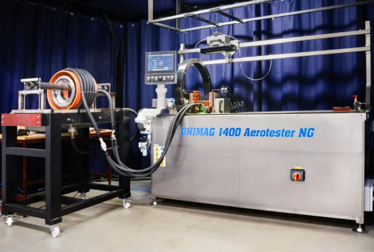
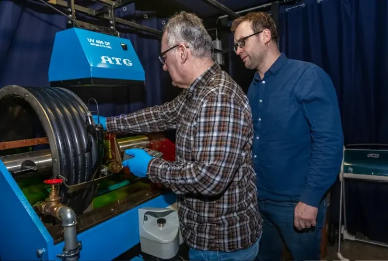
ATG develops and manufactures a range of customized automated UT systems (lines, manipulators) for rotational or longitudinal products (including specialized parts for the railway, automotive, and aerospace industries). UT systems are equipped with SOCOMATE UT cards allowing broad flexibility in system parameters’ modification.

ATG develops advanced MPI and FPI equipment and systems for high-precision inspection in production and maintenance and across multiple industries.
Explore automated testing of aircraft wheels and other ET solutions designed for reliable inspection in aerospace maintenance.
Advance your professional qualification through internationally recognized ASNT 9712 certification through ATG CERT.
Verify your NDT lab Proficiency by accredited Proficiency Testing Provider. Verification of NDT personnel proficiency is also available.

How Does Ultrasonic Inspection Work?

In ultrasonic testing, high-frequency sound waves are introduced into the material using a transducer, often with a couplant to ensure efficient transmission. The transducer converts electrical signals into sound waves and back into electrical signals as echoes return from internal reflectors, such as cracks, porosity, or inclusions. By analyzing the flight time and amplitude of these reflected echoes, operators can detect and characterize discontinuities, making UT a versatile tool for a wide range of materials, components, and industries.

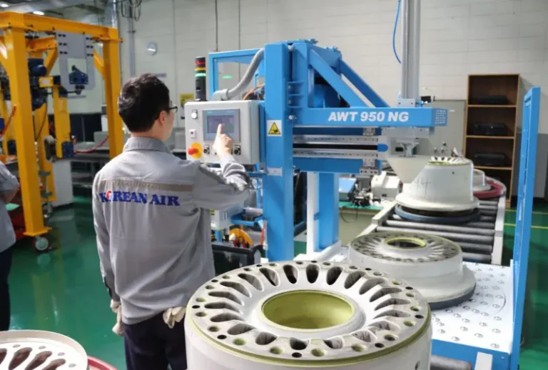
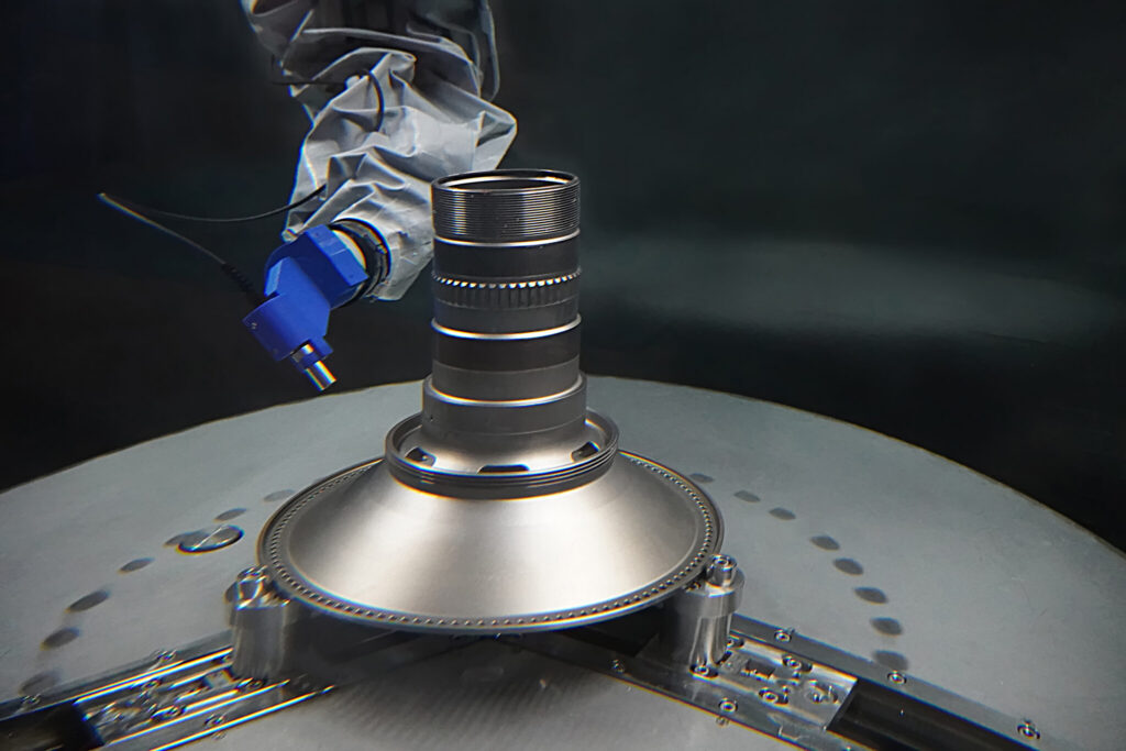
Automatic Ultrasonic system URM 360 testing a roller, tapered and cylindrical bearings with part dimensions min. inner rings ID from 110 mm and max. outer rings OD up to 360 mm.

Understanding Ultrasonic Testing in NDT

Ultrasonic testing (UT) is a non-destructive testing method that uses high-frequency sound waves to detect and characterize discontinuities in industrial components. By sending sound waves into a material and analyzing the echoes that return, technicians can identify internal defects and measure their parameters, such as length and size, and make an interpretation of material parameters, such as thickness. UT is highly versatile, with various techniques that make it suit a wide range of industries, such as the aerospace, automotive, or energy industries.

Ultrasonic Testing Equipment for Different Parts – Examples

Bearing rings

Fully automated ultrasonic testing line for bearing rings. URM 360 uses the immersion method and is well capable of detecting internal defects in bearing rings according to the standard EN 12080.

Application: Railways

Cylindrical roller bearings

The UZM 400 system is designed for fully automated testing of both inner and outer rings of cylindrical roller bearings. Its efficient design enables comprehensive ultrasonic testing with automatic loading, precise positioning, and automatic evaluation.

Application: Railway

Rotating aircraft engine parts

URM 1250 has been designed especially for testing rotating aircraft engine parts up to a maximum diameter of 1,250 mm. This system is ready to meet UT testing requirements of all major OEM and MRO organizations.

Application: Aerospace

Ultrasonic Inspection Systems and Equipment Delivered by ATG

ATG integrates UT systems with other NDT methods, e.g. MPI (for bearing rings inspection), or Eddy Current (bar/tube inspection). Thanks to these combined systems it is possible to reach high testing efficiency for the whole volume of products to be tested (combination of surface and volume method). ATG designs and produces its own scanning manipulators (mechanics + motion control) as well as data acquisition and post processing software for all industrial applications, for instance C-scan.

Ultrasonic testing with UZM 400: a clever solution for testing bearing rings in the railway industry

Ultrasonic Control – Types of Indication Display

A-scan

Basic display

B-scan

Displays the material section and requires probe motion information

C-scan

Displays the floor plan of the component under test., The indication position on the component is displayed and the size of the reflected indication is expressed in color

L-scan

Display typical of the Phased array technique, displays a set of A-scans transmitted by the PA probe at one angle in one probe position

S-scan

Display typical of the Phased array technique, displays in a color scale a set of A-scans transmitted by the PA probe at different angles in one probe position

TOFD

A set of non-rectified A-scans similar to B-scans, positive half-waves are displayed in lighter tones, negative half-waves are displayed in darker tones

UT and ASME Boiler and Pressure Vessel Code

In petrochemical facilities, ultrasonic testing (UT) plays a crucial role in ensuring the safety and reliability of pressure vessels, piping, and other critical infrastructure. Technicians regularly measure wall thickness and inspect for corrosion, wear, and cracks that can develop during routine operation or maintenance. Advanced UT methods, such as PAUT and TOFD, allow for precise weld inspections and detailed defect evaluation in new constructions. Compliance with industry codes—like ASME BPVC Section VIII and API standards 510 and 570—is mandatory, requiring that UT operators are fully trained and certified to carry out inspections according to strict safety and quality requirements.

Add Ultrasonic Testing Certification to Your Qualification

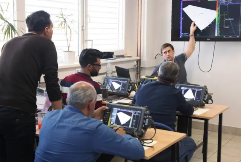
The deliveries of our UT systems are joined with the possibility to qualify NDT operators and provide on-the-job training in ATG Training Center where there are disposable training UT manipulators, or directly on equipment delivered to the customer ́s site.


In addition to personnel qualification, we also provide the development and implementation of testing procedures in accordance with specific customer requirements. Furthermore, we perform calibration of UT instruments used in UT systems, in compliance with relevant standards (e.g. ISO 22232-1).

Frequently Asked Questions (FAQ)

What are the different wave modes in Ultrasonic Testing (UT)?
In UT, different wave modes are utilized depending on inspection needs. Longitudinal waves travel fastest and can pass through solids, liquids, and gases.; Shear waves are highly sensitive for detecting small defects and are ideal for weld inspections.; Surface (Rayleigh) waves are confined to the material’s surface suited for detecting surface defects. Plate (Lamb) waves are for thin materials or bonded composites.
Ultrasonic testing enables volumetric inspection, detecting not only surface but also internal discontinuities, making it ideal for critical structural components. It is highly sensitive to defects, safe for operators since no radiation is involved, and portable enough for inspections in varied environments, all while providing fast and reliable results.
Ultrasonic testing can be challenging on complex geometries or materials that scatter or absorb ultrasound waves, and it requires good surface contact with a couplant for accurate results. Detection can also be affected by the orientation of discontinuity, and interpreting UT signals demands skilled, trained technicians.
Ultrasonic testing relies on sound waves reflecting off boundaries or discontinuities, refracting when entering materials at an angle, and penetrating into the material. By analyzing these behaviors, operators can accurately locate and characterize internal flaws without damaging the component.
A transducer is a device made of piezoelectric material that converts electrical impulses into ultrasonic sound waves and vice versa. In UT, technicians use transducers in pulse-echo mode — where a single transducer sends and receives waves to detect echoes from discontinuities — or in through-transmission mode, which uses separate send and receive transducers to identify defects via signal loss.
The immersion technique involves placing the part to test in a water tank and using waterproof transducers to send and receive ultrasonic waves through/from the material. This non-contact method is ideal for inspecting large metal or composite components in manufacturing and other industries.
PAUT uses multiple elements in a transducer to steer and focus ultrasonic waves, allowing for 3D imaging of discontinuities. This technique increases inspection reliability by providing detailed views of defects and their orientation within the material.
TOFD is an ultrasonic non-destructive testing method in which two probes are always used in a face-to-face configuration—one transmitting and one receiving. The transmitting probe generates a broad beam of longitudinal ultrasonic waves that propagate through the material toward the receiving probe. Flaw detection is based on the diffraction of ultrasonic waves at the edges of discontinuities (flaws), rather than on reflection as in the conventional pulse-echo technique. The signal is evaluated based on time of flight rather than amplitude, which ensures highly accurate flaw sizing. In addition, the method is relatively insensitive to flaw orientation because it captures waves diffracted from flaw tips. Therefore, TOFD enables very precise detection and sizing of internal flaws in materials.
The TOFD method has several significant advantages. Its flaw detection capability is largely independent of flaw orientation, ensuring reliable detection of discontinuities with various orientations. It is particularly effective at detecting flaws oriented perpendicular to the surface. Another advantage is the precise sizing of flaws, which is based on the flight time of ultrasonic waves. This method is also less sensitive to signal amplitude, meaning that probe coupling quality to the material is not as critical as in other techniques. System setup is almost independent of weld geometry, which makes it easy to use in a wide range of practical applications. A significant benefit is also the ability to obtain a permanent digital record of the inspection results, enabling subsequent data archiving and analysis.

Learn More

Check out our other systems and equipment for non-destructive testing.

Contact Us

Contact us, we’ll be happy to answer.