Hello EN
Welcome to WordPress. This is your first test post. You can edit or delete it, and then start building your own website.
ATG designs and manufactures its own Fluorescent Penetrant Inspection (FPI) lines for highly sensitive detection of surface defects, primarily for the aerospace industry, in accordance with ASTM E1417 and, where required, other customer‑specific or industry standards. ATG also delivers high‑performance, fully automated FPI lines for applications in the automotive industry.
Most delivered solutions are engineered precisely to customer requirements, taking into account inspection capacity, dimensions of tested parts and the selected material handling concept. Available solutions include manual lines (LPM) with overhead hoists or roller tracks, as well as automated lines (LPC) using partially or fully automated conveyor or crane‑based handling systems.

Liquid penetrant inspection is a non‑destructive testing (NDT) method based on the penetration of a liquid penetrant into defects that are open to the surface of the inspected component. After application of the penetrant to a properly prepared and cleaned surface, the penetrant enters cracks, pores, and other surface‑breaking discontinuities by means of capillary action.
After the specified penetration (dwell) time, during which the penetrant enters potential discontinuities, excess penetrant is removed from the surface and a developer is subsequently applied to facilitate the formation of indications.
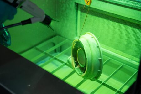
The use of fluorescent penetrants, which are generally more sensitive than visible color‑contrast penetrants, requires evaluation of the resulting indications under ultraviolet (UV) radiation. This ensures high sensitivity of the method and enables detection of even very fine surface defects.
Cleaning of components before and after inspection is a fundamental and inseparable requirement of the FPI method. Inspected parts must be sufficiently clean and dry prior to testing to allow proper penetrant penetration into defects. Likewise, final cleaning after inspection ensures removal of residual penetrant materials and prepares components for subsequent manufacturing operations or safe return to service.
Fluorescent or Dye Penetrant Inspection (FPI / DPI) is a non‑destructive testing (NDT) method used to detect surface‑breaking defects in solid, non‑porous materials.
FPI (Fluorescent Penetrant Inspection) uses fluorescent penetrants and provides higher inspection sensitivity, while DPI (Dye Penetrant Inspection) uses visible color‑contrast penetrants, typically red, evaluated under white light.
The inspection principle is based on applying a liquid penetrant to the surface of a tested component. Due to capillary action, the penetrant penetrates surface‑breaking discontinuities such as cracks or pores. After removal of excess penetrant, a developer is applied, drawing penetrant back to the surface and forming visible indications.
In the case of fluorescent penetrants, the indications appear as bright yellow‑green fluorescing traces under ultraviolet (UV) light, significantly improving the detectability of even very fine surface‑breaking defects.
FPI is widely used in industries such as aerospace, automotive, medical technology and power generation, where it contributes to quality assurance, safety and reliability of inspected components.
Application: Aerospace
Application: Aerospace industry (MRO and OEM)
Application: Automotive industry
Application: Aerospace, power generation, and heavy industry
Process water treatment, including conditioning of inlet water and processing of FPI wastewater
Surface preparation, such as pickling prior to FPI, including associated water treatment and wastewater neutralization
Degreasing prior to FPI as a prerequisite for reliable inspection
Integrated conveyor and material handling systems
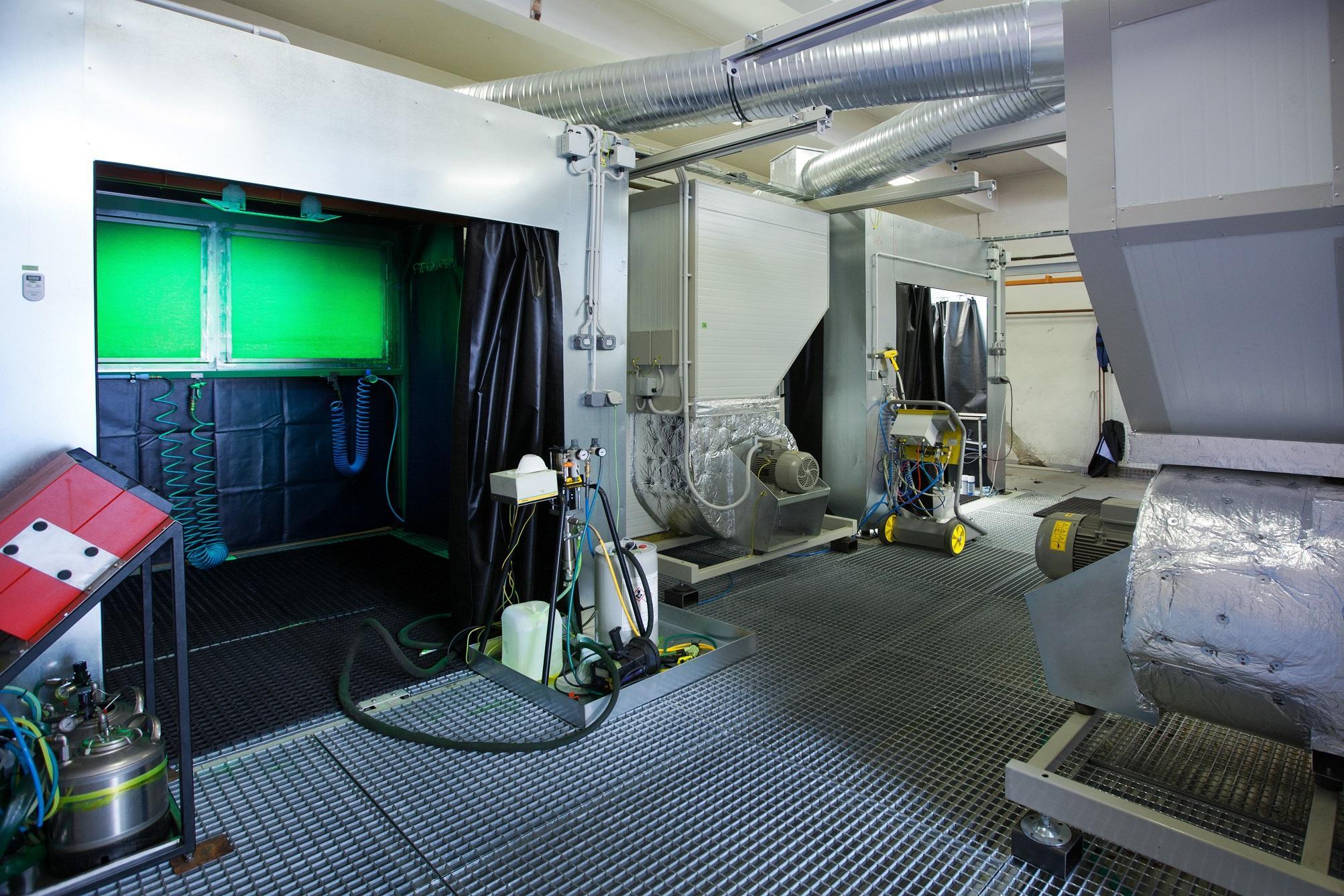
Exhaust air extraction and filtration from process cabins and tanks
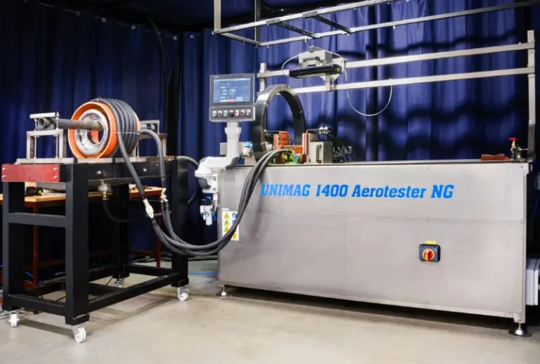
The LPM 320 / 530 FPI line is manufactured from stainless steel for maximum durability and long‑term operational reliability. It is available in various tank sizes and penetrant/developer application variants, including immersion, electrostatic application and vortex cabinets. Thanks to its modular design, the line can be flexibly adapted to customer requirements and complies with common industrial standards across aerospace and other industries.
Welcome to WordPress. This is your first test post. You can edit or delete it, and then start building your own website.
Implementing a new penetrant inspection (FPI) line represents a significant investment and is often associated with a complex decision‑making process for many customers. During this process, avoidable mistakes are frequently made, which can be eliminated through a structured and informed approach.
The following overview summarizes the most common challenges and provides recommendations for the successful implementation of a liquid penetrant inspection system.
Incompatible part flow or line layout relative to process requirements
Insisting on handling methods unsuitable for part weight or geometry.
Underestimating space requirements for installation or part handling
Incorrect part flow before or after the FPI process.
Incompatibility with current or future products.
Incorrect size of process tanks or cabins.
Limiting the primary decision criterion to price only, without considering the technical solution, operating costs, and other relevant parameters
Insufficient technical expertise within the decision-making team, particularly when internal FPI specialists are not involved
Failure to involve external FPI consultants in situations where internal know-how is insufficient
Inadequate qualification of operating and maintenance personnel, which can negatively affect system operation and long-term reliability
Overly detailed RFQs focused on minor technical details, where critical conceptual and operational requirements may be overlooked
Frequent changes of responsible personnel during the procurement and implementation process, leading to a loss of continuity and project knowledge
Late project initiation and prolonged negotiation phases, ultimately limiting the available time for high-quality project execution
Involve internal FPI specialists or external consultants with PT Level 3 certification
Collect detailed information on current and future parts, including capacity and dimensional reserves
Review applicable customer and end-user standards to avoid the design of incompatible solutions
Standardize consumables where possible thereby simplifying both the technical solution and future operation.
Verify maximum part dimensions for future applications
Compile detailed FPI process data for all parts
Review available installation space and utility connection points
Design part flow according to the expected technological process in accordance with the expected process flow wherever feasible.
Ensure trained and qualified personnel are available prior to start-up
Review local regulations related to wastewater treatment and air emissions
Select the appropriate application technique for penetrants and developers based on part type; each method has specific advantages and limitations
Consider Automatic Defect Recognition (ADR) to improve efficiency and repeatability
Our Fluorescent Penetrant Inspection (FPI) lines are designed and delivered to meet all relevant technical standards and requirements of the aerospace industry and to enable operation in environments with accreditation demands. ATG systems comply with widely used aerospace standards, particularly ASTM E1417, and are engineered to support operation within NADCAP‑accredited processes, as well as to meet customer‑specific and manufacturing requirements.
An example is the LPM 2600max, developed for the Australian company TAE Aerospace for MRO of civil and military aircraft engines. The line complies with ASTM E1417 requirements for both MRO and OEM applications and is designed in accordance with the requirements of a NADCAP‑accredited process. At the same time, it meets specific requirements of aircraft engine manufacturers such as Rolls‑Royce, GE Aviation, Pratt & Whitney, Honeywell, Safran, and others.
Beyond the aerospace sector, ATG FPI lines are also designed for customers operating in the automotive industry, power generation, mechanical engineering and other industrial sectors, where penetrant inspection is subject to different standards and specific requirements. ATG solutions can comply with standards such as EN ISO 3452, AMS, ASME, as well as other industry‑specific, corporate or individual customer specifications.
Thanks to a modular system design and long‑term experience in FPI technology development, ATG is able to adapt its technical solutions to specific standard‑related, process and operational requirements, both for serial production and for small‑batch or custom inspections. This ensures a high level of system flexibility and applicability across a wide range of industrial applications.
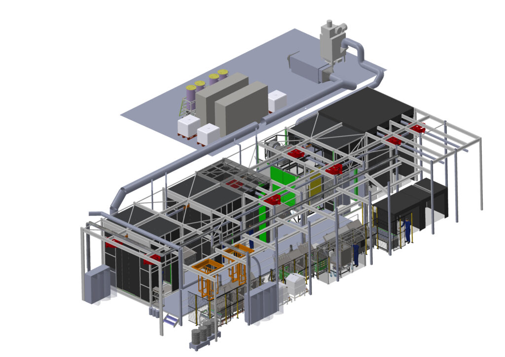
This year, ATG is implementing the largest FPI line installation in its history. The system is being delivered for an aerospace MRO company and consists of two FPI lines supported by complete auxiliary technologies.
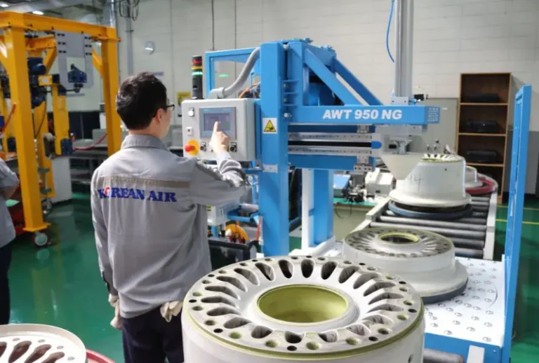
The first line is fully automated, equipped with an automated conveyor, and intended for inspection of small and geometrically simple parts, evaluated by qualified inspectors.
The second line is designed for manual inspection of medium and large parts with diameters of up to 2,000 mm. It features a rail system with electric hoists and switches, providing high flexibility in part movement along the line.
The complete system includes exhaust air filtration and a wastewater treatment system using ultrafiltration and activated carbon.
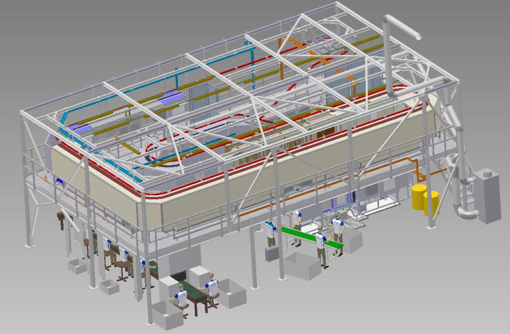
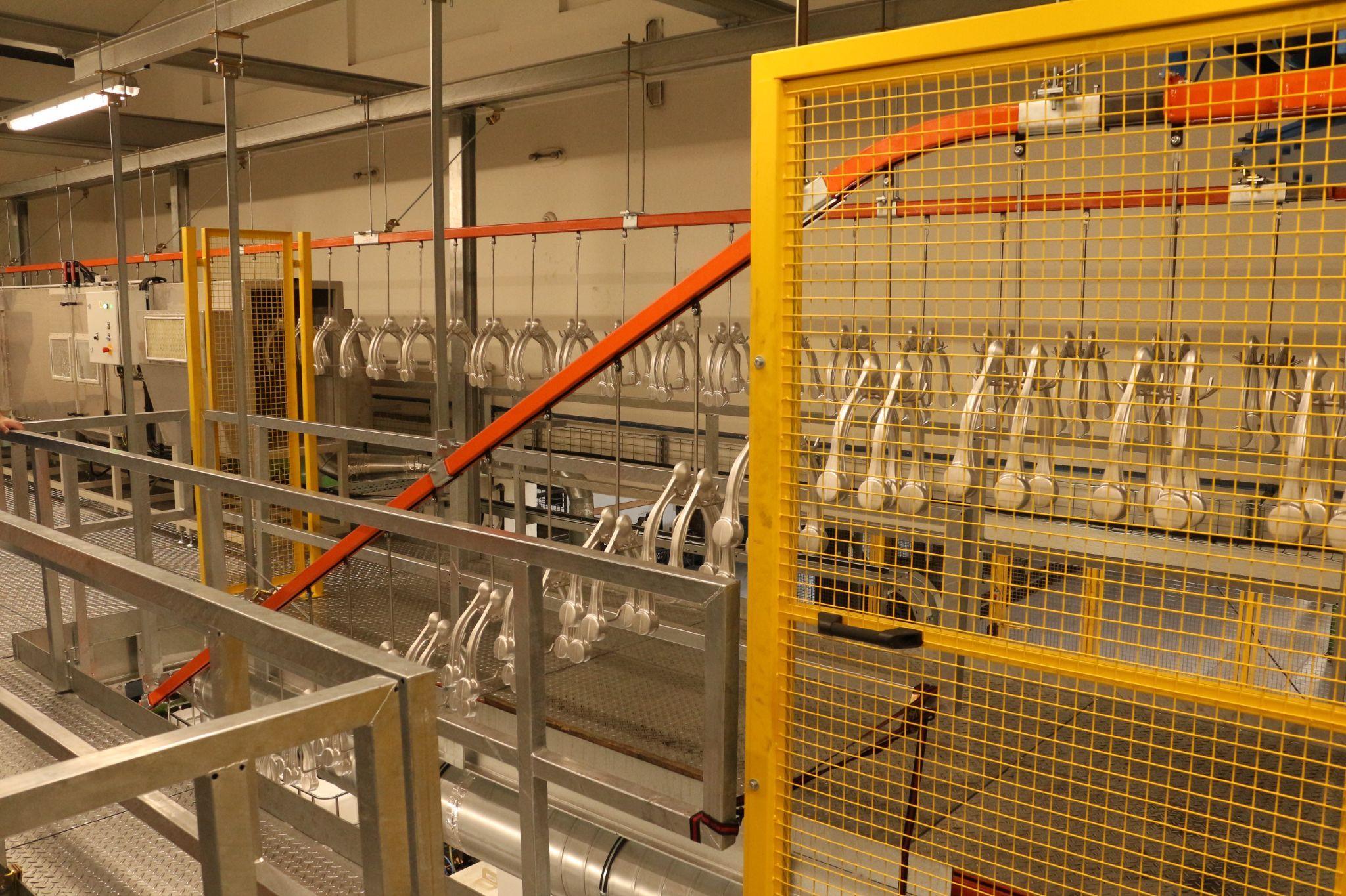
For a major manufacturer of aluminum forgings in the Czech Republic, ATG delivered an FPI line for inspection of chassis components with a capacity of up to 900 parts per hour. To optimize space utilization in the production hall, the line is arranged as a two‑level system interconnected by a conveyor.
The line is equipped with an enclosed continuous chain conveyor that moves parts at a constant speed between individual stations of the penetrant inspection process.
Penetrant application is carried out using electrostatic spraying, followed by rinsing with adjustable water spray nozzles. Parts are then dried with hot air while passing through a circulation dryer, after which the developer is applied in a vortex (spray) chamber.
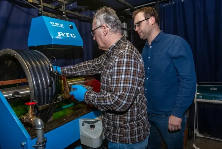
As the final step, components are evaluated in an inspection cabin under ultraviolet (UV) light.
FPI lines of this type are prepared for integration of Automatic Defect Recognition (ADR) as well as for automated part loading and unloading, enabling further increases in efficiency and inspection repeatability.
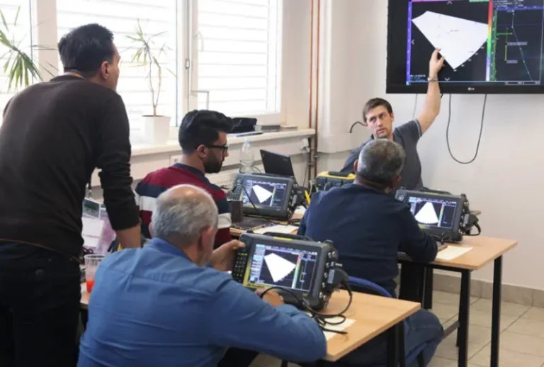
Delivery of ATG penetrant inspection (FPI) lines can be complemented by qualification of NDT operators and the provision of practical professional training. Training is conducted at the ATG Training Center, where fully operational FPI and DPI lines are available for instructional purposes, enabling hands‑on training under real operating conditions.
One of these training lines is approved for inspection of parts from aircraft engine manufacturers Rolls‑Royce, GE Aviation and Pratt & Whitney and is operated within a NADCAP‑accredited process.
Upon customer request, training can also be carried out directly on the delivered equipment at the installation site, taking into account the specific technical configuration and applied FPI process.
Fluorescent penetrant Inspection (FPI), also known as liquid penetrant testing, is a highly sensitive non‑destructive testing (NDT) method used for the detection of surface‑breaking defects in solid, non‑porous materials. The method enables reliable identification of defects open to the surface, such as cracks, pores, lack of fusion, laps, seams, and leak paths.
The FPI process is based on the application of a liquid penetrant to the surface of the inspected part, using immersion, spraying, or electrostatic application. The penetrant enters surface discontinuities, which are subsequently made visible after the application of a developer in the form of clearly defined indications. These indications are then evaluated under ultraviolet (UV) light, allowing for reliable assessment even of very fine surface defects.
Fluorescent Penetrant Inspection (FPI) systems are particularly critical for the aerospace industry, where they are used for high‑sensitivity inspection of safety‑critical components in compliance with standards such as ASTM E1417 and additional customer‑specific requirements. In aerospace applications, the FPI method is a standard inspection technique used both in original equipment manufacturing (OEM) and in maintenance, repair and overhaul (MRO) of aircraft components.
Beyond aerospace, FPI systems are also widely applied in other industrial sectors, especially in the automotive industry, power generation and mechanical engineering, as well as in the manufacture of pressure‑bearing and safety‑critical components. In these applications, FPI systems serve as high‑performance production‑integrated or inspection lines, tailored to specific process and operational requirements.
ASTM E1417 is an international technical standard issued by ASTM International that defines the basic requirements and procedures for performing liquid penetrant nondestructive testing (NDT) of materials. The standard specifies the minimum requirements for the inspection of non‑porous metallic and non‑metallic components.
It describes penetrant inspection processes used during manufacturing, final acceptance, and in‑service inspections to detect defects such as cracks, lack of fusion, porosity, or surface‑open corrosion.
The document serves as a framework practice and also establishes terminology, essential test conditions, and highlights safety, material, and application limitations associated with the use of penetrant inspection materials.
Certainly. In many applications, traditional manual FPI lines can be replaced by fully automated systems equipped with conveyor‑based material handling. Automation enables increased inspection capacity, process repeatability, and overall process stability, particularly in serial production environments.
In addition, selected lines can be equipped with Automatic Defect Recognition (ADR) systems, which utilize specialized camera systems and artificial intelligence (AI) to automatically detect and evaluate defect indications. These technologies can significantly improve inspection efficiency, reduce dependence on subjective operator evaluation, and enhance the consistency and traceability of inspection results
Penetrant removers and emulsifiers are used to remove excess penetrant from the surface of the inspected part after the specified dwell time. Their correct application is essential to ensure the quality and reliability of penetrant inspection results.
The purpose of these materials is to clean the surface without removing the penetrant retained in the surface‑breaking defects. As a result, penetrant remains only within cracks and other surface discontinuities, from where it can subsequently be drawn back to the surface by the developer, forming clear, readable and high‑contrast indications.
The selection of the appropriate penetrant removal method—water‑washable systems or post‑emulsifiable systems using hydrophilic or lipophilic emulsifiers—depends on the specific FPI system used, the type of inspected parts and the required inspection sensitivity.
During liquid penetrant inspection (LPI/FPI), two basic types of penetrants are used: visible (color‑contrast) and fluorescent penetrants. The selection of penetrant type depends on the required inspection sensitivity, applicable standards, and inspection conditions.
a. Visible (color‑contrast) penetrants
Visible penetrants are evaluated under white light and are primarily suitable for less demanding applications, maintenance activities, or inspection of small production batches.
b. Fluorescent penetrants
Fluorescent penetrants provide higher inspection sensitivity and are evaluated under ultraviolet (UV) light or radiation. They are predominantly used in the aerospace industry and other safety‑critical applications.
Penetrants are further classified according to the method used to remove excess penetrant from the surface:
a. Water‑washable penetrants
b. Post‑emulsifiable penetrants (using hydrophilic or lipophilic emulsification)
Penetrant application can be performed using several methods, depending on part geometry and the configuration of the FPI line:
a. Immersion
b. Spraying
c. Electrostatic application
The proper selection of penetrant type and application method has a significant impact on inspection sensitivity, result repeatability, and overall efficiency of the FPI process.
During liquid penetrant testing, a developer is applied after the removal of excess penetrant. Its purpose is to draw penetrant out of surface‑breaking defects and to form visible indications suitable for evaluation.
The most commonly used developer types include:
a. Dry powder developers
b. Aqueous developers in the form of a solution
c. Aqueous developers in the form of a suspension
d. Solvent‑based developers (nonaqueous developers – NAWD), which are also commonly used for verification of the relevance of indications
The correct selection of the developer type has a crucial influence on indication contrast, inspection sensitivity, and the overall reliability of liquid penetrant inspection results.
In the aerospace industry, liquid penetrant inspection (FPI) is used to detect surface‑breaking defects, particularly cracks, fatigue cracking, corrosion, and other surface discontinuities that may adversely affect the safety, integrity, and service life of components. The FPI method is applied to the inspection of a wide range of aerospace components, including turbine blades and other aircraft engine components, landing gear parts, and additional safety‑critical structures.
FPI is used both in manufacturing (OEM) and during maintenance, repair, and overhaul (MRO) operations, in compliance with applicable aerospace standards and accreditation requirements.
Liquid penetrant testing represents a highly versatile non‑destructive testing (NDT) method that can be applied to a wide range of non‑porous materials, including metals, plastics and ceramics. The FPI method is characterized by its high sensitivity to very fine surface defects, is cost‑effective, and provides results that are easy to interpret.
Thanks to its flexibility, penetrant inspection is suitable both for on‑site inspections and for efficient batch testing of large quantities of parts. Within a single inspection cycle, multiple smaller components can be tested simultaneously, contributing to higher productivity and overall process optimization.
Liquid penetrant testing is limited to the detection of surface‑breaking defects and does not allow identification of internal or subsurface discontinuities. For this reason, the FPI method is not suitable for testing porous materials, as the penetrant may infiltrate the material structure itself and thereby mask or distort actual surface defects, leading to unreliable inspection results.
To achieve reliable and reproducible results, the method also requires thorough cleaning and drying of the inspected surfaces and that inspections be carried out under controlled inspection conditions, particularly with regard to lighting, environmental cleanliness, and strict adherence to prescribed process steps.
Wetting ability (wettability) describes how effectively a liquid penetrant can spread over and uniformly cover the surface of an inspected part. Good wetting ability is an essential prerequisite for the proper function of the FPI method, as it ensures continuous contact between the penetrant and the surface and enables its reliable penetration into surface‑breaking defects.
Insufficient wetting ability, on the other hand, leads to the formation of droplets or isolated areas of penetrant, which can result in incomplete surface coverage and, in extreme cases, the overlooking of fine surface defects. Wetting quality is influenced primarily by surface cleanliness, the type of material, and the properties of the penetrant used.
This non‑destructive testing method is suitable for most non‑porous materials, including metals, ceramics, and certain types of plastics. However, liquid penetrant inspection is not effective for porous materials, as the penetrant can penetrate into the material structure itself and thereby mask or distort actual surface defects, leading to unreliable inspection results.
Check out our other systems and equipment for non-destructive testing.